
Boolean Logic
| Home | Order | Let me know what you think |
Control and embedded systems frequently deal with individual bits in order to control specific operations or to determine the condition of part of a system. For example, a bit might be turned on to light a lamp or activate a relay, or a bit might be off to indicate a switch is on (off meaning on is very common due to the nature of hardware -- order some and see what I mean).
Boolean logic, developed by George
Boole (1815-1864), is often used to refine the determination of system
status or to set or clear specific bits. Boolean logic is simply a way
of comparing individual bits. It uses what are called operators to determine how the bits are
compared. They simulate the gates
that you will see in the hardware section you will read shortly.
Think of operators as boxes with multiple inputs and one output. Feed in various combinations of bit values, and the output will be high or low depending on the type of operation. The examples show 2 inputs, although gates can have more. Also, gates are often combined to form more complex logic. A modern microprocessor contains huge numbers of them with many inputs and many varying combinations. Please note that the terms on, high and 1 will be considered the same logical state, and off, low and 0 will be considered the same logical state in the discussions that follow.
The operators used most often are AND
and OR. The AND operation says if and only if all inputs are on, the output will be on. The
output will be off if any of the inputs are off. The OR operation says if any input is on, the output will be on. It's
easy to see all of the combinations by using what are called truth tables, illustrated below. At the bottom
of each table is shown the schematic symbol found in circuit diagrams.
|
|
||||||||||||||||||||||||||||||||||||||||||
There are two operations that have the same logic as above, but with
an inverted output. The NAND operation
says if and only if all inputs are on, the output will be off. The output will be on if any of
the inputs are off. The NOR
operation says if any input is on, the output will be off. Notice the bubble on the output of the
schematic symbol used to indicate an inversion.
|
|
||||||||||||||||||||||||||||||||||||||||||
There is a variation on the OR logic called Exclusive OR or XOR. Exclusive OR says the output will be on if the inputs are different.
Another one, the inverter or NOT operation, says that the output will be
opposite in state to the input. It obviously has only one input and one
output. Note that it will change an AND to a NAND, an OR to a NOR and an
XOR to a NXOR if connected to their outputs. It simply changes 1s to 0s
and 0s to 1s.
|
|
|||||||||||||||||||||||||||||
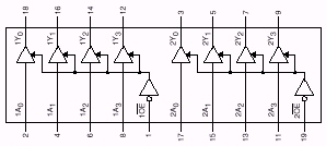
One other basic digital device is on the board. It actually performs no logic. It looks like an inverter without the bubble, and is called a buffer. It's a triangle with a single input and output. It is not used for logic, but to increase the output drive capability of a line, or to lighten the load seen by circuits outside of ours. This is sometimes called repowering. Some buffers have a third line entering the side of the triangle. When it is not activated, the output of the buffer is removed from the circuit to keep it from interfering with other devices. The 74LS244 is an example:
In C, symbols are substituted for the full description or
abbreviation of a Boolean operation. They are as follows for the
operations covered:
| Logical Operation | Abbreviation | Symbol |
| And | AND | & |
| Or | OR | | |
| Exclusive OR | XOR | ^ |
| Inversion | NOT | ~ |
It is common in the C language to perform logical operations on bytes or words. Combinations of on and off conditions are often important determinants of condition, and the use of logical combinations as outputs can be used to cause complex actions. To determine the result when logical operations are applied to larger variable types, simply work with one bit at a time. Some examples follow. The numbers are presented in both hexadecimal and binary form. The top line shows an equation illustrating the operation in hexadecimal notation and the symbol used in C. It is not a C statement, but simply an illustration of the action taken. The three lines following it show the numbers used in the operation and the result in both HEX and binary. The first example is expanded to show how the result is determined one bit at a time.
0xC1 & 0xEA = 0xC0 (this says 0xC1 AND 0xEA = 0xC0)
0xC1 11000001 (the two nibbles are 1100 = 12 = 0xC and 0001 = 1 = 0x1)
0xEA 11101010
0xC0 11000000
||||||||_ 1 AND 0 = 0
|||||||__ 0 AND 1 = 0
||||||___ 0 AND 0 = 0
|||||____ 0 AND 1 = 0
||||_____ 0 AND 0 = 0
|||______ 0 AND 1 = 0
||_______ 1 AND 1 = 1
|________ 1 AND 1 = 10x00 & 0x86 = 0x00 (this says 0x00 AND 0x86 = 0x00)
0x00 00000000
0x86 10000110
0x00 00000000 (Think, "This bit will be on
only if both of the ones above it are on.")0x88 & 0xE0 = 0x80 (this says 0x88 AND 0xE0 = 0x80)
0x88 10001000
0xE0 11100000
0x80 10000000
0xC0 | 0xAD = 0xED (this says 0xC0 OR 0xAD = 0xED)
0xC0 11000000
0xAD 10101101
0xED 11101101 (Think, "If either one of the bits above is on,
this one will be on.")0xAD | 0xEF = 0xEF (this says 0xAD OR 0xEF = 0xEF)
0xAD 10101101
0xEF 11101111
0xEF 111011110xC4 | 0x84 = 0xC4 (this says 0xC4 OR 0x84 = 0xC4)
0xC4 11000100
0x84 10000100
0xC4 11000100
0xD4 ^ 0x8D = 0x59 (this says 0xD4 XOR 0x8D = 0x59)
0xD4 11010100
0x8D 10001101
0x59 01011001 (Think, "This bit will be on only if the two above it are
not the same.")0xDA ^ 0x87 = 0x5D (this says 0xDA XOR 0x87 = 0x5D)
0xDA 11011010
0x87 10000111
0x5D 010111010xAB ^ 0xFC = 0x57 (this says 0xAB XOR 0xFC = 0x57)
0xAB 10101011
0xFC 11111100
0x57 01010111
~0x86 = 0x79 (this says 0x86 inverted = 0x79)
0x86 10000110
0x79 01111001 (Think, "This is all of the bits above reversed.")~0xC1 = 0x3E (this says 0xC1 inverted = 0x3E)
0xC1 11000001
0x3E 00111110~0xEA = 0x15 (this says 0xEA inverted = 0x15)
0xEA 11101010
0x15 00010101
The following is a self-test over this section. It would be a very good idea to make sure you know the answers to all of the questions since the sections that follow will build on this one.
1)It was developed by George Boole, and is often used to refine the determination of system status or to set or clear specific bits.
A) On
B) NXOR
C) Boolean Logic
D) AND
2) Boolean Logic uses __1__ to determine how bits are compared and simulates __2__ .
A) Operators, Gates
B) Buffers, AND
C) Truth Tables, Off
D) NOR, NAND
3) The _____ operation says if and only if all inputs are on, the output will be on. The output will be off if any of the inputs are off.
A) OR
B) NAND
C) NOR
D) AND
4) The _____ operation says if any input is on then the output will be on.
A) NOT
B) OR
C) NOR
D) XOR
5) If and only if all of the inputs are on, the output will be off. This is called _____ .
A) NAND
B) NOR
C) Truth Tables
D) On
6) This operation says that if any input is on, the output will be off. What operation is this?
A) Boolean Logic
B) XOR
C) NOR
D) AND
7) _____ says that if the inputs are different then the output will be on.
A) Gates
B) Low
C) NXOR
D) XOR
8) _____ simply changes the input to the opposite (0 to 1 or 1 to 0).
A) Operator
B) NOT
C) AND
D) OR
9) 0xB0 & 0xD9
Operator: __________
Binary for 0xB0: __________
Binary for 0xD9: __________
Result of Operation: __________
10) 0xAF | 0x9C
Operator: __________
Binary for 0xAF: __________
Binary for 0x9C: __________
Result of Operation: __________
11) 0xC3 ^ 0x7C
Operator: __________
Binary for 0xC3: __________
Binary for 0x7C: __________
Result of Operation: __________
12) ~0x85
Operator: __________
Binary for 0x85: __________
Result of Operation: __________
| Order | Home |