| Home | Order | Let me know what you think |
This experiment shows how to use analog to control a PWM channel. The TIP120 darlington transistor (see TIP120.PDF) will be used here as it was in Experiment 5.
The TO-220 package of the TIP120 is shown again below. Remember that the tab is connected to the collectors of the transistors, so if the heat sink is grounded the tab must be insulated from the heat sink but still conduct heat to it.

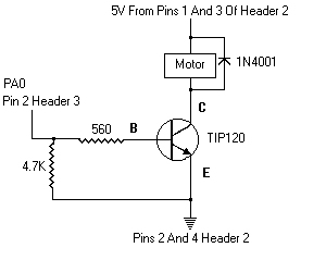
The wiring of the motor, the TIP120 and the PPI is shown below as it
was in Experiment 5, except that the
TIP120 is shown as a single transistor, which is common in many
schematics:
NOTE: Please be sure to read the Warranty And Disclaimer before working with the hardware!
The output control header module has been changed to modify the structure for setting up an analog channel:
  // outct10a.h

  .........

  struct anachan
  {
    int status;
    int last_value;
    int current_value;
    int controls_PWM;
    int PWM_channel;
    int arraynumber;
    int NoiseBand;
  };
  .........

  // end outct10a.h
|
The status element in the structure funtions the same as before. It provides information about whether a channel is active and, if so, if a conversion should start or if data is ready. As might be expected, the current conversion value is stored in current_value. The values of last_value, NoiseBand and current_value determine if there is a need to set up a new PWM for a motor. A change is made to the PWM duty cycle only if the current and last values differ from each other by at least the amount in the NoiseBand element.
The controls_PWM element can assume one of three values. If it's 0, the analog channel does not control a digital channel. If it's 1, the channel determines a uni-directional PWM value only in the forward direction. If it's 2, it provides bi-directional PWM control. The uni-directional mode will be covered in this experiment. The PWM_channel is the same as the Forward Port Number, such as PA0, PB1, etc., and the arraynumber is the Output Control digital array location.
The following shows the changes to TurnOnAnalog(..) in the timer header and C modules:
  // timer10a.h

  .........

int TurnOnAnalog(int channel, // analog channel number
                 int type, // 0=no digital control, 1=forward, 2=bi-directional
                 int arraynumber, // output control array number
                 int ForwardPortNumber, // port bit for forward control
                 int NoiseBand); // current and last reading must differ by
                                 // this much for PWM change to take place

  .........

  // end timer10a.h
|
// timer10a.c

.........

int TurnOnAnalog(int channel, // analog channel number
                 int type, // 0=no digital control, 1=forward, 2=bi-directional
                 int arraynumber, // output control array number
                 int ForwardPortNumber, // port bit for forward control
                 int NoiseBand) // current and last reading must differ by
                                // this much for PWM change to take place
{
  if(channel < 0 || channel > 7)
    return -1;

  AnnalogChannel[channel].status = START_CONVERSION;

  if(type)
  {
    AnnalogChannel[channel].controls_PWM = type;
    AnnalogChannel[channel].PWM_channel = ForwardPortNumber;
    AnnalogChannel[channel].arraynumber = arraynumber;
    AnnalogChannel[channel].NoiseBand = NoiseBand;
    AnnalogChannel[channel].last_value = 0;
  }

  DA_Enabled = 1;

  return channel;
}

.........

// end timer10a.c
|
An example of a call to TurnOnAlanalog(..) might be:
TurnOnAnalog(0, 1, MainMotor, PA0, 2);
The call is for analog channel 0 to have uni-directional control for Output Control array number MainMotor (defined in an enumeration) which will use PA0 to control a motor. Changes will not occur until current and last analog values are at least 2 apart.
The following is the new analog part of the interrupt service routine in the timer C module:
// timer10a.c

.........

  if(DA_Enabled) // is DA section enabled?
  {
    // look for start conversion or data ready status
    while(!AnnalogChannel[CurrentChannel].status)
    {
      CurrentChannel++;
      if(CurrentChannel > 7)
        CurrentChannel = 0;
    }

    switch(AnnalogChannel[CurrentChannel].status)
    {
      case START_CONVERSION:
        // will be ready at next interrupt, so say so
        AnnalogChannel[CurrentChannel].status = DATA_READY;
        break;

      case DATA_READY:
        // check eoc even though it's probably already ready
        while(!(inp(eoc) & 0x80));

        // load data into structure
        AnnalogChannel[CurrentChannel].current_value = inp(base);

.........

// end timer10a.c
|
To test it, run the following and vary the offset control:
// exper10a.c

#include "exper10a.h"

enum
{
  MainMotor,
  LED1,
  LED2,
  LASTSLOT
};

void main(void)
{
  int x;
  double dc,oldfreq,newfreq;

  oldfreq = 1193180.0/65536.0;

  set_up_new_timer(1000.0);

  newfreq = get_frequency();

  printf("old frequency = %f new frequency = %fHz\n"
  ,oldfreq,newfreq);

  x = (int)InitializeAnalog();

  printf("init ana = %X\n",x);

  // make everthing an output
  set_up_ppi(Aout_CUout_Bout_CLout);

  x = TurnOnAnalog(0, // analog channel number
                   1, // 0=no digital control, 1=forward, 2=bi-directional
                   MainMotor, // output control array number
                   PA0, // port bit for forward control
                   6); // current and last reading must differ by
                       // this much for PWM change to take place

  Blink(LED1,PA1, .03, .02);

  Blink(LED2,PA2, .3, .2);

  printf("TurnOnAnalog(..); = %d\nPress any key to continue then any key to quit -- no Ctr-C!\n",x);

  getch();

  while(!kbhit())
    CheckAnalog(0);

  portaoff();

  // be sure to restore the timer!
  restore_old_timer();
}

void CheckAnalog(int anachan)
{
  if(abs(AnalogChannel[anachan].current_value -
         AnalogChannel[anachan].last_value) >
         AnalogChannel[anachan].NoiseBand)
    {
//      printf("last = %d current = %d\n"
//      ,AnalogChannel[anachan].current_value
//      ,AnalogChannel[anachan].last_value);

	  AnalogChannel[anachan].last_value =
      AnalogChannel[anachan].current_value;

      if(AnalogChannel[anachan].controls_PWM == 1) // unidirectional
      {
        UniPwmDuty(AnalogChannel[anachan].arraynumber,
                   AnalogChannel[anachan].PWM_channel,
                  (double)AnalogChannel[anachan].current_value/255.0);
//        printf("duty=%4.3f",(double)AnalogChannel[anachan].current_value/255.0);
//        show(anachan);
      }
    }
}

// end exper10a.c
|
Take a look at the CheckAnalog(..) function. The last value is set equal to the current value provided the current value is at least as far away from the last value by the amount contained in the NoiseBand element. Notice the use of the abs() function. It will return the positive value of an integer regardless of its sign. For example, abs(30) = abs(-30) = 30.
If all conditions are met and the controls_PWM element is also set to 1, a call is made to UniPwmDuty(..) to change the duty cycle of the control channel located at arraynumber using the port designated by PWM_channel.
The duty cycle is the current value divided by the maximum analog value of 255.
The idea behind not changing speed unless the difference is outside NoiseBand is to avoid noise on a channel caused by such things as electrical and mechanical interference. A NoiseBand value of only 1, for example, causes the motor to change speeds erratically. A value of 10 provides speed changes in steps. Download exper10b.c and exper10c.c below to see the effect.
Click here to download timer10a.c
Click here to download timer10a.h
Click here to download exper10a.c
Click here to download exper10a.h
Click here to download extrn10a.h
Click here to download outct10a.h
Click here to download const10a.h
Click here to download digi10a.h
Click here to download exper10b.c
Click here to download exper10c.c